14 Mayıs 2015 Perşembe

Automatic plant watering project on Arduino

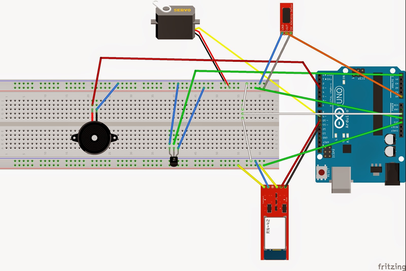
     In this project our aim is to build an automatic watering system with using hydrometer sensor and arduino in the basis. System gets the information about humidity from hydrometer sensor in the soil and starts to water if plant becomes dry and thirsty to keep it alive. Auto Plant project has also temperature sensor for measuring the temperature in the air and alarm and automatic email service to warn the owner if water is finished. This project was built on Arduino IDE and with using hydrometer sensor, wifi module, temperature sensor, servo, buzzer and Arduino Uno board.


Equipment List:
·        YL-69 Soil Hydrometer Humidity Detection Module
·        ESP8266 Serial WIFI Module
·        LM35 Temperature Sensor
·        Servo
·        Arduino Uno
·        Buzzer
·        Server
·        Jumpers

·        Board

      We designed the project according to an idea which is about keeping the plants living with automatic running system. This system can be used by people who has limited time and who has to travel frequently. So, we took this idea as an infrastructure for the project and we designed an automatic watering system with some equipment which is convenient to use with Arduino. First we figured out which kind of warning system can be useful. We built an email service with using ESP8266 wifi module and we send a message for the owner with the information about water in the system and temperature. The project has two measured part which is temperature and humidity, so our smart system measures them in every five minutes. We store the information about normal humidity level and temperature rate on EEPROM and when system read the values then it compares them.
               An automatic watering system is activated when water level is under the normal level. Movement is provided by servo and some other equipment. Water is filled by the owner and system starts an alarm if watering action is not handled. We designed the alarm time as playing 3 times in 1 minute interval. When the user doesn’t fill the water then system sends an email to the owner.

               In the designing part, we chose the TimerOne library for interrupts and time intervals. Also we thought EEPROM was convenient for the project as a storage position to keep the normal values of humidity and temperature.

Requirements :

Project has overall six requirements in particular areas:

-        In extra, hydrometer sensor, wifi module, temperature sensor and buzzer will be used in this project.

-        In this project, EEPROM will be used to keep the plant moisture ratio and temperature level that it requires. Data will be used in comparison of read value which comes from sensor reading and normal value which is called from EEPROM.

-        Humidity level will be measure in every 5 minutes to understand it is under the normal level or not. So, timer will be used to check the time.

-        To avoid the plant dead if water in the mechanism is done, buzzer will start as an alarm until 5 minutes pass.

-        Owner will be warned by the system with the information of temperature and humidity ratio when they are not good for the plant. It will be done by wifi module and connecting with the server. For example when the temperature decreased below the normal value or humidity level then owner will be warned with using the email message.

-        System will water the plant automatically when the humidity level is less. So, movement will be done by the servo. It will be connected with the Arduino and also it has a connection with a container filled with water.


Arduino Code : 

#include <SoftwareSerial.h>
#include <Servo.h>
#include <TimerOne.h>

#define DEBUG true

SoftwareSerial esp8266(10,11); //TX RX
Servo servo;
int hydrometerSensor = 0;
int lm35Pin = 5;
int buzzerPin = 3;
int duration=1000;
int frequency = 262;
int hydrometerValue;
int hydrometerValue2;
float temperature;
int flag = 0;
int checkBuzz;
int count = 0;
int checkServo = 0;
int info; //water is finished info = 1, temp is low info = 0

void setup(){
  
  servo.attach(9);
 // analogReference(INTERNAL);
  pinMode(buzzerPin, OUTPUT);
  Timer1.initialize(8000000);
  Timer1.attachInterrupt(reread);
  Serial.begin(9600);
  esp8266.begin(9600);

}
void loop(){
  int time1, time2;

 if(checkBuzz == 1){
   if(count>2){
     noTone(buzzerPin);
     info = 1;
     sendEmail(info);
     count = 0;
     checkBuzz = 0;
   }
   else{
      buzz();
      count++;
   }
  
 }

 if(hydrometerValue>900){
     //servo
    delay(5000);
    hydrometerValue2 = analogRead(hydrometerSensor);
    if(hydrometerValue2>900){
      checkBuzz = 1;
    }
    else{
      checkBuzz = 0;
    }
 }

 /*if(temperature < 10){
   info = 0;
   sendEmail(info);
 }*/
}


void reread(){
  /*if(flag<15){
    flag++;
  }
  else{*/
    hydrometerValue = analogRead(hydrometerSensor);
    int reading = analogRead(lm35Pin);
    temperature =  (reading*5.0*100.0)/1024.0;
     Serial.print("hydro  : ");
  Serial.println(hydrometerValue);
  Serial.print("temp  : ");
  Serial.println(temperature);
   // flag = 0;
  //}
  //Serial.println(sensorValue);
  //340 - 1023
}

void buzz(){
  for(int i = 0;i<10;i++){
    tone(buzzerPin, frequency, duration/2);
    delay(duration);
  }
}

void sendEmail(int info){
   
   String response;
   String cmd = "AT+CIPSTART=4,\"TCP\",\"yeicmobil.com\",80\r\n";  //make this command: AT+CPISTART="TCP","146.227.57.195",80
   String val =  "GET http://www.yeicmobil.com/android/cse342.php?email=email@email.com&data=";
   val=val+info;
   val=val+" HTTP/1.0\r\n\r\n"; //construct http GET request
   String value = "AT+CIPSEND=4,";
   value=value+val.length();
   value=value+"\r\n";
   
  sendData("AT+RST\r\n",2000,DEBUG);
  sendData("AT+CWMODE=1\r\n",1000,DEBUG);
  sendData("AT+RST\r\n",2000,DEBUG);
  sendData("AT+CIPMUX=1",500,DEBUG);
  response=sendData("AT+CWJAP=\"modem\",\"password\"\r\n",2000,DEBUG);
  response=sendData(cmd,2000,DEBUG);
  response = sendData(value,2000,DEBUG);
  sendData(val,5000,DEBUG);
  
}
String sendData(String command, const int timeout, boolean debug){
    String response = "";
    esp8266.print(command); // send the read character to the esp8266
    long int time = millis();
    while( (time+timeout) > millis())
    {
      while(esp8266.available())
      {
        // The esp has data so display its output to the serial window 
        char c = esp8266.read(); // read the next character.
        response+=c;
      }  
    }
    if(debug)
    {
      Serial.println(response);
    }
    return response;
}


Playing notes with using buzzer and softpotentiometer

This example makes use of a Piezo Speaker in order to play melodies. We are taking advantage of the processors capability to produde PWM signals in order to play music. With using soft potentiometer, we can change buzzer tone note. In this modification buzzer plays notes in an order according to the softpotentiometer value. 


All notes are defined in the below : 
#define NOTE_B0  31
#define NOTE_C1  33
#define NOTE_CS1 35
#define NOTE_D1  37
#define NOTE_DS1 39
#define NOTE_E1  41
#define NOTE_F1  44
#define NOTE_FS1 46
#define NOTE_G1  49
#define NOTE_GS1 52
#define NOTE_A1  55
#define NOTE_AS1 58
#define NOTE_B1  62
#define NOTE_C2  65
#define NOTE_CS2 69
#define NOTE_D2  73
#define NOTE_DS2 78
#define NOTE_E2  82
#define NOTE_F2  87
#define NOTE_FS2 93
#define NOTE_G2  98
#define NOTE_GS2 104
#define NOTE_A2  110
#define NOTE_AS2 117
#define NOTE_B2  123
#define NOTE_C3  131
#define NOTE_CS3 139
#define NOTE_D3  147
#define NOTE_DS3 156
#define NOTE_E3  165
#define NOTE_F3  175
#define NOTE_FS3 185
#define NOTE_G3  196
#define NOTE_GS3 208
#define NOTE_A3  220
#define NOTE_AS3 233
#define NOTE_B3  247
#define NOTE_C4  262
#define NOTE_CS4 277
#define NOTE_D4  294
#define NOTE_DS4 311
#define NOTE_E4  330
#define NOTE_F4  349
#define NOTE_FS4 370
#define NOTE_G4  392
#define NOTE_GS4 415
#define NOTE_A4  440
#define NOTE_AS4 466
#define NOTE_B4  494
#define NOTE_C5  523
#define NOTE_CS5 554
#define NOTE_D5  587
#define NOTE_DS5 622
#define NOTE_E5  659
#define NOTE_F5  698
#define NOTE_FS5 740
#define NOTE_G5  784
#define NOTE_GS5 831
#define NOTE_A5  880
#define NOTE_AS5 932
#define NOTE_B5  988
#define NOTE_C6  1047
#define NOTE_CS6 1109
#define NOTE_D6  1175
#define NOTE_DS6 1245
#define NOTE_E6  1319
#define NOTE_F6  1397
#define NOTE_FS6 1480
#define NOTE_G6  1568
#define NOTE_GS6 1661
#define NOTE_A6  1760
#define NOTE_AS6 1865
#define NOTE_B6  1976
#define NOTE_C7  2093
#define NOTE_CS7 2217
#define NOTE_D7  2349
#define NOTE_DS7 2489
#define NOTE_E7  2637
#define NOTE_F7  2794
#define NOTE_FS7 2960
#define NOTE_G7  3136
#define NOTE_GS7 3322
#define NOTE_A7  3520
#define NOTE_AS7 3729
#define NOTE_B7  3951
#define NOTE_C8  4186
#define NOTE_CS8 4435
#define NOTE_D8  4699
#define NOTE_DS8 4978

with these notes, each song can be played with using buzzer on Arduino.


Arduino Code : 

const int buzzer=9;
const int softPin=0;

const int songLength = 2;

char notes[]="c";
int freqValue;
void setup(){
  pinMode(buzzer, OUTPUT);
}
void loop(){

 int sensorValue;
 int duration=1000;
 
 sensorValue=analogRead(softPin);
 freqValue=trans(sensorValue);
 tone(buzzer, freqValue, duration);
 delay(duration);
}

int trans(int sensorValue){
  int freq;
  freq=map(sensorValue, 0, 1023, 31, 4978);
 
return freq;

Simple fire alarm system with using LM35 and buzzer

Fire alarm system is active when temperature is greater than 50C degree. In this modification we used also TimerOne library for reading the temperature in every 5 seconds. It is modifiable for other projects.

Equipments  :
 - LM35 Temperature Sensor pin
 - Buzzer
 - Arduino Uno
 - Breadboard
 - Jumper Wires


Arduino Code : 

#include <TimerOne.h>
int lm35Pin = 0;
int buzzerPin = 3;
int duration=1000;
int frequency = 262;
float tempVal;
int val;
int flag = 0;

void setup(){
  pinMode(buzzerPin, OUTPUT);
  Timer1.initialize(500000);
  Timer1.attachInterrupt(readTemp);
  Serial.begin(9600);
}
void loop(){
  if(val>10){
    Serial.println("Temperature is to high, fire might be occured!!");
    Serial.println(val);
    buzz();
  }
}
void readTemp(){
  flag++;
  if(flag==12){
    tempVal = analogRead(lm35Pin);
    val = tempVal/2;
   // val = (5.0*100.0)/1024.0;
    flag = 0;
    Serial.print("Temp  :");
    Serial.println(val);
  }
}
void buzz(){
  for(int i = 0;i<4;i++){
    tone(buzzerPin, frequency, duration/2);
    delay(duration);
  }
}


12 Mayıs 2015 Salı

Sending an email with using ESP8266 Wifi module

ESP8266 is a very useful and cheap wifi module to be as client, server and access point.

ESP8266 Quick Starter Guide : http://rancidbacon.com/files/kiwicon8/ESP8266_WiFi_Module_Quick_Start_Guide_v_1.0.4.pdf

!!!BE CAREFUL, ESP8266 WORKS UNDER 3.3 VOLT NOT 5 VOLT!!!

For sending an email, we used our server and PHP code. PHP code file is in the server file system and wifi module makes a connection with the PHP code.

PHP code :

<?php
include('DatabaseConnection.php');
$data=$_GET['data'];
$email=$_GET['email'];
require /*write here php file directory*/;
$mail = new PHPMailer;

//$mail->SMTPDebug = 3;                               // Enable verbose debug output

$mail->isSMTP();                                      // Set mailer to use SMTP
$mail->Host = 'localhost';  // Specify main and backup SMTP servers
$mail->SMTPAuth = true;                               // Enable SMTP authentication
$mail->Username = /*write here SMTP username*/;                 // SMTP username
$mail->Password = /*write here SMTP password*/;                           // SMTP password
//$mail->SMTPSecure = 'tls';                            // Enable TLS encryption, `ssl` also accepted
//$mail->Port = 587;                                    // TCP port to connect to

$mail->From = (/*write here host name*/);
$mail->addAddress($email);               // Name is optional
$mail->WordWrap = 50;     
$mail->isHTML(true);                                  // Set email format to HTML

$mail->Subject = /*write here mail subject*/;
$mail->Body    = /*write here mail message*/;
$mail->AltBody = /*write here altbody*/;

if($mail->send()) {
   $flag['code']=1;
}else{
   $flag['code']=0;
}
print(json_encode($flag));
mysql_close();
?>

Arduino Code :

#include <SoftwareSerial.h>
SoftwareSerial esp8266(10,11); //TX RX
#define DEBUG true

void setup()
{
  Serial.begin(9600); //serial debug
  esp8266.begin(9600); 
  //set mode needed for new boards
  
}

void loop()
{
  
  WebRequest();
  delay(5000);
}

//web request needs to be sent without the http for now, https still needs some working
void WebRequest(){

   String response;
   String cmd = "AT+CIPSTART=4,\"TCP\",\"WRITE HERE HOST NAME\",80\r\n";  //make this command: AT+CPISTART="TCP","146.227.57.195",80
   String val =  "GET /*WRITE HERE FILE NAME OF PHP*/";  //construct http GET request
   String value = "AT+CIPSEND=4,";
   value=value+val.length();
   value=value+"\r\n";
   
  sendData("AT+RST\r\n",2000,DEBUG);
  sendData("AT+CWMODE=1\r\n",1000,DEBUG);
  sendData("AT+RST\r\n",2000,DEBUG);
  sendData("AT+CIPMUX=1",500,DEBUG);
  response=sendData("AT+CWJAP=\"WIFI ACCESS POINT NAME\",\"WIFI ACCESS POINT PASSWORD\"\r\n",2000,DEBUG);
  response=sendData(cmd,2000,DEBUG);
  response = sendData(value,2000,DEBUG);
  sendData(val,5000,DEBUG);
  
}
String sendData(String command, const int timeout, boolean debug)
{
    String response = "";
    
    esp8266.print(command); // send the read character to the esp8266
    
    long int time = millis();
    
    while( (time+timeout) > millis())
    {
      while(esp8266.available())
      {
        
        // The esp has data so display its output to the serial window 
        char c = esp8266.read(); // read the next character.
        response+=c;
      }  
    }
    
    if(debug)
    {
      Serial.println(response);
    }
    
    return response;
}
boolean Contains(String s, String search) {
    int max = s.length() - search.length();

    for (int i = 0; i <= max; i++) {
        if (s.substring(i) == search) return true; // or i
    }

    return false; //or -1


Led On-Off via bluetooth and android

In this modification, we built bluetooth connection with android mobile device. On android side, there is a android code and simple user interface. Arduino code has led on-off code and bluetooth code.
Arduino code includes "SoftwareSerial.h" library. This library is in arduino automatically. We should define as include this library at first. Bluetooth communication is done with Serial Port of the Arduino IDE adn bluetooth device.
Bluetooth device is 4.0 and mobile device must has 4.0 bluetooth for matching.

On the figure, you can see connection of the equipment :


Android code link : https://github.com/olimpias/BluetoothConnection

Arduino code :

#include <SoftwareSerial.h>  

int bluetoothTx = 11;  // TX-O pin of bluetooth mate, Arduino D2
int bluetoothRx = 10;  // RX-I pin of bluetooth mate, Arduino D3
int ledPin = 13;
SoftwareSerial bluetooth(bluetoothTx, bluetoothRx);
int lightStatus = 'c';
void setup()
{
  Serial.begin(9600);  // Begin the serial monitor at 9600bps
  pinMode(ledPin,OUTPUT);
  // 115200 can be too fast at times for NewSoftSerial to relay the data reliably
  //Setup Bluetooth serial connection to android
  bluetooth.begin(115200);
  bluetooth.print("$$$");
  delay(100);
  bluetooth.println("U,9600,N");
  bluetooth.begin(9600);
}

void loop()
{
  if (Serial.available() > 0) {
    // read the oldest byte in the serial buffer:
    lightStatus = Serial.read();
    bluetooth.println(lightStatus);
    // if it's a capital R, reset the counter
  }
  
  if(bluetooth.available() > 0){
    lightStatus = bluetooth.read();
    if ( lightStatus == 'c'){
      digitalWrite(ledPin,LOW);
    }
    if (lightStatus == 'o'){
      digitalWrite(ledPin,HIGH);
    }
  }
  // and loop forever and ever!
}


Setting servo speed with using push buttons

In this modification, servo speed is changed via 2 push buttons. One button increases the speed, other one decreases it.
Circuit is shown in the below :

Servo and two push buttons


CODES :


#include <Servo.h> 
const byte buttonPin[2]={2,3};
const byte servoPin = 9;
int servoSpeed = 100;
const byte minLimit = 0;
int servoPosition = 0;
boolean servoIsHigh = false;
// Create a servo "object", called servo1. Each servo object
// controls one servo (you can have a maximum of 12):

Servo servo1;
void setup(){
  Serial.begin(9600);
  servo1.attach(servoPin);
  servoPosition = servo1.read();
}
void loop(){
  
  if (!digitalRead(buttonPin[0])){
    servoSpeed = servoSpeed + 10;
    delay(20);
  }
  if(!digitalRead(buttonPin[1])){
    servoSpeed = servoSpeed - 10;
    if(servoSpeed < minLimit){
      servoSpeed = minLimit;
    }
  }
    Serial.print("Speed Servo");
    Serial.println(servoSpeed);
    Serial.print("Servo position");
    Serial.println(servoPosition);
    delay(20);
    servo1.write(servoPosition);
    if(servoPosition > 180){
      servoIsHigh=true;
    }
    if(servoPosition < 0){
      servoIsHigh=false;
    }
    if(servoIsHigh){
          servoPosition-=10;

    }else{
          servoPosition+=10;

    }
    delay(servoSpeed);


}


Led delays according to the temperature sensor and its brightness changes due to photo sensor value.
Photo sensor and temperature sensor are connected with analog pins of Arduino. Photo sensor values are mapped into leds brightness value and temperature is mapped into time intervals.
In the below code sample and video is shown :


Codes:

const byte sensorPin=0,sensorTemp=1;
const byte ledPin=11;
int lightLevel,low=300,high=1000,tmpLevel;
void setup()
{
  // We'll set up the LED pin to be an output.
  // (We don't need to do anything special to use the analog input.)
  Serial.begin(9600);
}
void loop(){
  lightLevel=analogRead(sensorPin);
  tmpLevel=analogRead(sensorTemp);
  Serial.print("Analog Read Value ");
  Serial.println(lightLevel);
  Serial.print("Temp read value ");
  Serial.println(tmpLevel);
  float voltage = getVoltage(tmpLevel);
  float degreesC = (voltage - 0.5) * 100.0;
  Serial.print("  deg C: ");
  Serial.println(degreesC);
  tune();
  digitalWrite(ledPin,HIGH);
  analogWrite(ledPin,lightLevel);
  delay(tmpLevel*10);
  digitalWrite(ledPin,LOW);
    delay(tmpLevel*10);
}

void tune(){
  lightLevel=map(lightLevel,low,high,0,255);
  Serial.print("Light map value = ");
  Serial.println(lightLevel);
  lightLevel=constrain(lightLevel,0,255);
  Serial.print("Light constrain value = ");
  Serial.println(lightLevel);
}
float getVoltage(int tmp_Level)
{

  return (tmp_Level * 0.004882814);

}

To adjust brightness with leds and buttons

Brightness can be adjusted by buttons. One button increases the brightness, other decreases.


Code is in the below :

const int ledPin = 11;
const int button1= 2;
const int button2 = 3;
byte brightness[] = {0, 30, 100,180,255}; //these are brightness levels, they can be changed
byte state=0;
void setup()
{
  // initialize the serial communication:
  Serial.begin(9600);
  // initialize the ledPin as an output:
  pinMode(ledPin, OUTPUT);
  pinMode(button1,INPUT);
  pinMode(button2,INPUT);
}
void loop() {
 
  if(!digitalRead(button1)){//button pressed
    if(state<4){
     state++;
     analogWrite(ledPin, brightness[state]);
     Serial.println("High brightness");
     delay(250);
    }
  }
  else if(!digitalRead(button2)){//button pressed
    if(state>0){
      state--;
      analogWrite(ledPin, brightness[state]);
      Serial.println("Low brightness");
      delay(250);
    }
  }
  Serial.println(state);
  Serial.println(brightness[state]);


}


11 Mayıs 2015 Pazartesi

Touchscreen with leds


Leds with Soft Potentiometer Circuit Design
This circuit is designed for switching leds by values that come from soft potentiometer.
Values are mapped according to the number of leds.
Code are shown in below :

/*soft potentiometer with leds*/
const int SENSOR_PIN = 0;
 byte ledPins [7];


void setup()
{
  int i;
  Serial.begin(9600);
  for (i=0;i<7;i++){
    ledPins[i] = i+2;
    pinMode(ledPins[i],OUTPUT);
  }
}
void loop(){
  int sensorValue ;
  sensorValue = analogRead(SENSOR_PIN);
  Serial.print("Sensor Value ");
  Serial.println(sensorValue);
  int openPin = map(sensorValue,0,1023,-1,7);
  Serial.print("pin is ");
  Serial.println(openPin);
  int i;
  for(i=0;i<7;i++){
    if(i == openPin){
      digitalWrite(ledPins[i],HIGH);
    }else{
      digitalWrite(ledPins[i],LOW);
  }
  }
}

Leds and softpotentiometer connection